
Safe driving thanks to robust inclination sensors
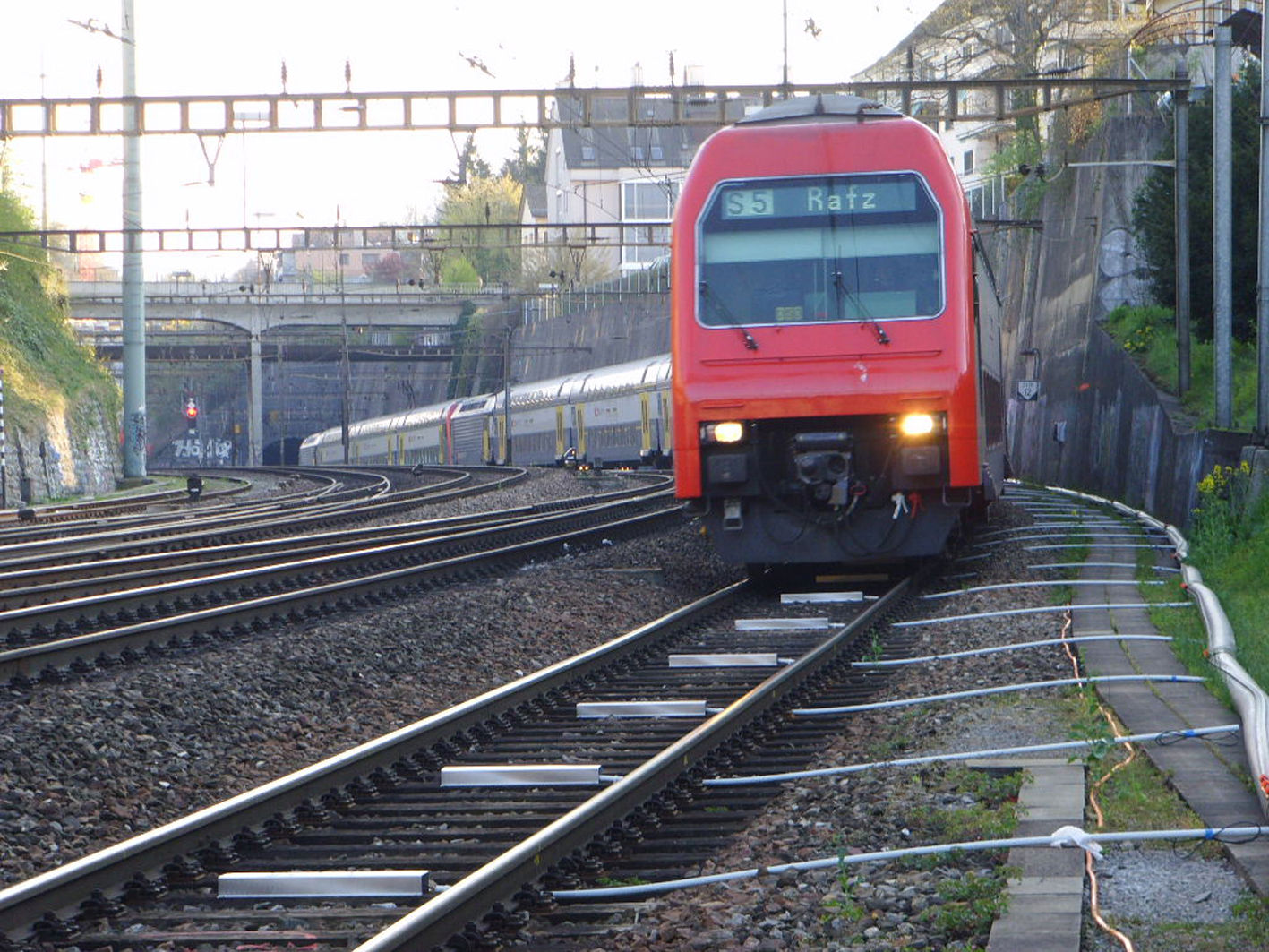
In order to reduce the amount of traffic in Traunstein city centre, the construction of a bypass was started in the spring of 2009. In order to do this, the railway line from Munich to Salzburg had to be crossed using a tunnel, amongst other things. Continuous monitoring of the railway track was required by Deutsche Bahn (DB) during the construction of the underpass. The engineering office responsible for the planning, Bernd Gebauer GmbH from Traunstein, decided to install a monitoring system for safeguarding the track system during the construction work by engineers from ing Traunreut GmbH. The individual combinable measuring sensors from Leica Geosystems with the LeicaGeoMoS or GeoMoS Web monitoring software were all but predestined for this.
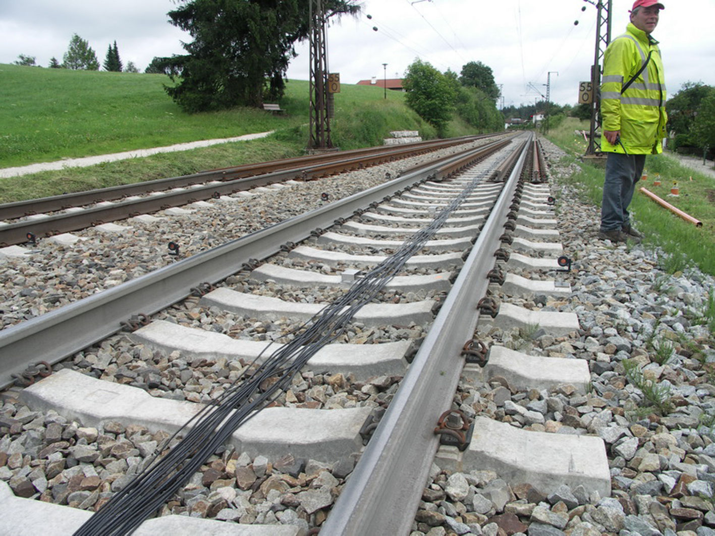
The measuring system that was installed included the Leica total stations TCA1800 and also the testing the new Leica TM30 tachymeter, which had been specially developed for the monitoring. These motorised sensors provide continuous measurement with documentation round the clock for 100 prisms which are attached directly to the structure. Meteorological sensors, a web cam and 38 inclination sensors were also installed. The tachymeters were placed onto pillars about 3 metres in height in the non-settling area and protected from the weather, vandalism and theft using a specially manufactured housing.
General monitoring system requirements
Because of the strict regulations of DB, the monitoring system that was used had to fulfil extremely high demands. On the one hand, measuring accuracy of ±0.3 mm/m was required from the inclination sensors that were used, and on the other hand accuracy of ±1.0 mm had to be provided by the tachymeter measurements. In order for a system such as this to operate reliably, the storage and backing up of the measuring data is extremely important. For example, as well as the fixed data cable (DSL), a fall-back system was also installed which maintains the data transfer via UMTS in the event of an emergency. The measuring systems must also cover any power failures using an independent uninterruptible power supply (UPS) system. In the event of the tolerance being exceeded, the responsible DB train dispatchers will be notified by text message. The option of notification via a landline was also set up for this case.
The goal was to generate an alarm signal for more exact checking of the situation in the event of lateral sleeper inclination of more than 3 mm (approx. 0.12°).
In order to do this, 2-axis inclination sensors were needed that are robust to impacts and vibration when trains pass over, and can withstand large temperature differences (-40…+85°C) and moisture (IP67 tightness). High reproducibility (< 0.03°) without hysteresis and a high degree of long-term stability (< 0.03° / annum) were also important. The choice was made for the inclination sensor with current output from a.b.jödden gmbh.
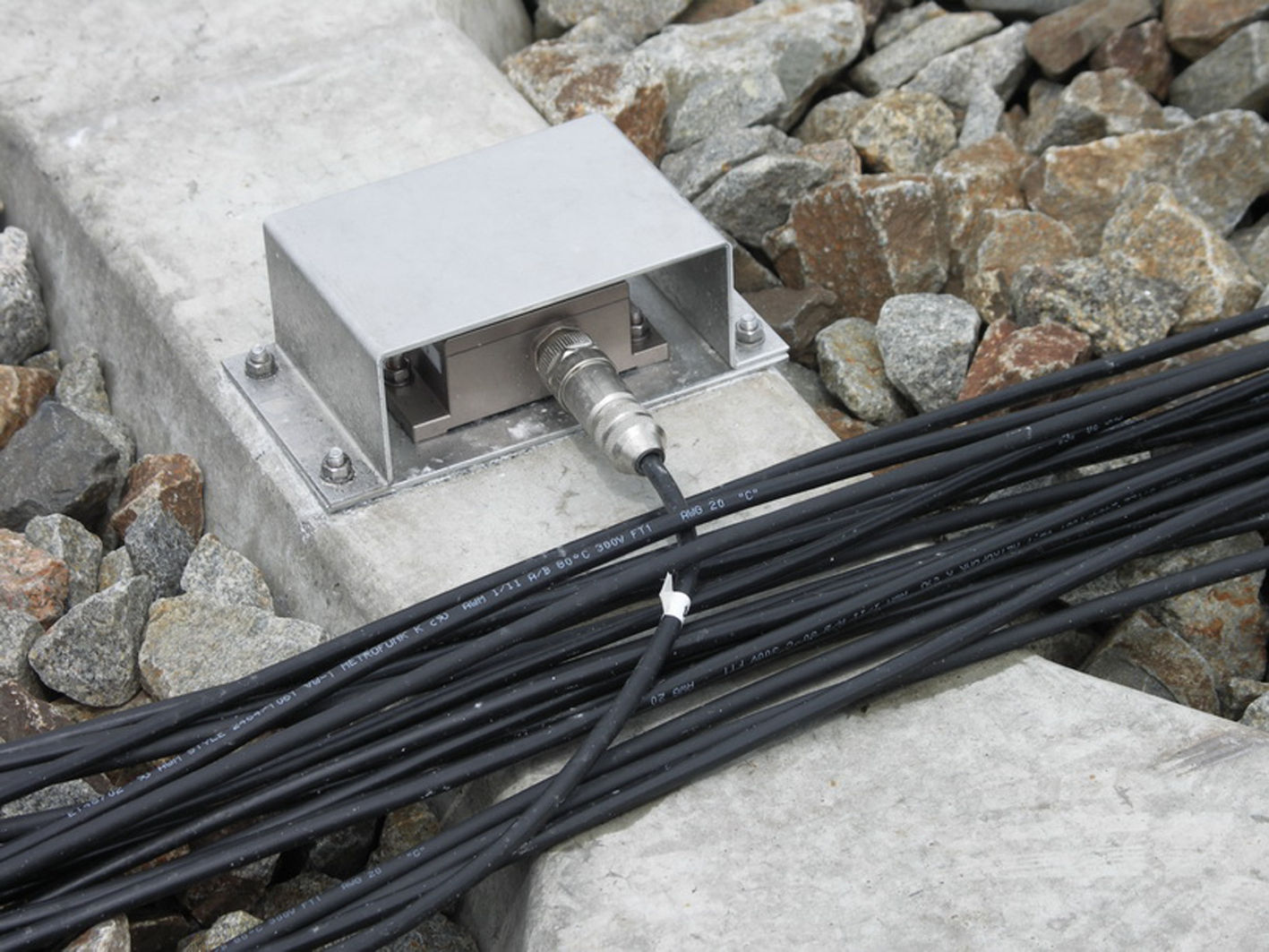
The sensors were protected from stone impacts and direct sunlight (up to +80°C) by a suitable sheet metal panel. The current interfaces were connected to the data logger system using PUR cables. These monitor and collect the data. The strong vibrations of the trains (= rapid “inclination changes”) are measured by the sensor at 1 Hz and also filtered by the data logger system.
Thanks to the internal temperature compensation and the highly reproducible capacitive silicon technology, it was possible to attain accuracy ranges that had been previously unachievable. If precision inclinometers with 2-dimensional multi-point calibration had been used, the costs would have been 3 to 5 times higher. It would also have been uncertain whether such highly sensitive sensors could have withstood the severe impacts and vibration of the railway without drift.
The cost-effective and robust inclination sensors can also be used for acceleration and vibration measurements, since different measuring ranges (up to 12 g) and measuring frequencies (bis 400 Hz) can be provided. This may open up new possibilities in applications such as geotechnical engineering, building monitoring, machine monitoring, measurements in public vehicles etc.
Measuring principle:
The flywheel (“pendulum”) method is basically is basically used. This means that a test mass is moved by either acceleration or vibration. The test mass is arranged between two capacitor plates, and changes the capacitive values. This well-tried method is particularly used in cases where the accuracy requirements are high or external influences such as temperature, vibration and shock are to be brought under control.
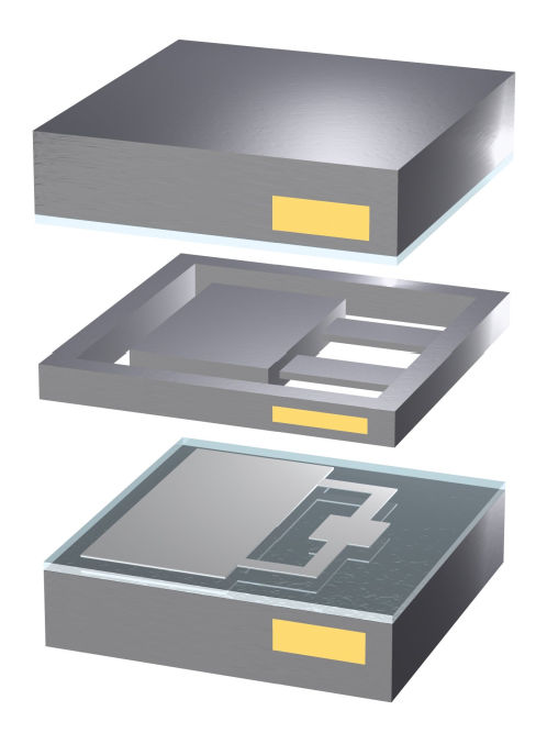
Schematic diagram of a sensor element: In the middle area you can see the pendulum, which is enclosed in the upper and lower plate (wafer) and forms a capacitor.
Repeat accuracy of better than 0.03° and resolutions of better than 0.003° can be achieved with this technology.
Because of the special design, no drift due to deformation of the test mass is anticipated, even in the event of hard impacts (up to 70,000 g). The gas damping inside the sensor element prevents resonance frequencies and overshooting.
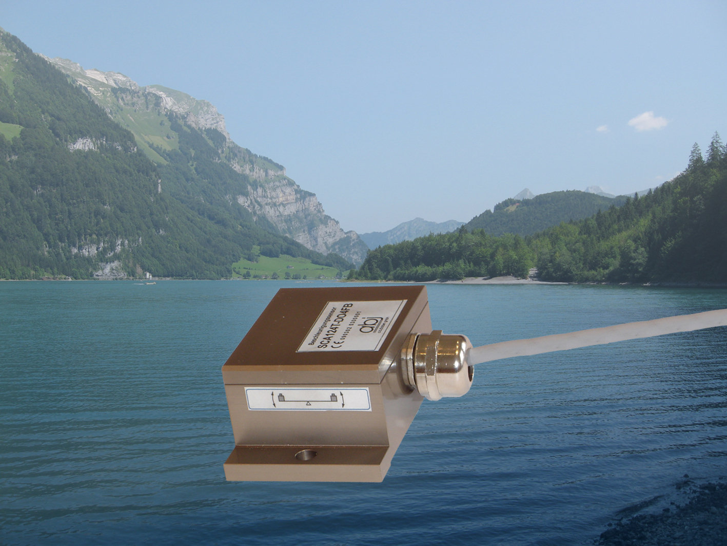
The sensor, which is installed in the robust IP68-protected housing, is easy to install using 3 screw holes and connected using a PG screw connection and PUR cables.
Proof of capability for use underwater was provided by submerging an inclination sensor at a depth of 10 m for 5 weeks in the Klöntalersee in Switzerland.
The 4 ... 20 mA signal output also makes it possible to use longer connecting cables. The current signal can be optionally converted into a voltage signal of 1 … 5 or 2 … 10 V using an appropriate resistor.
Inclination sensors (optionally 1 or 2 axis) with ranges of ±30° (=±0.5 g) or ±90° (=±1 g) are available as standard.
All sensors are calibrated to 1g/0°, or optionally to ±45°. This means that basically, no additional zero point calibration is required (apart from mechanical adaptations in the application).
Sensors with a measuring range of ±12 g are available for acceleration and vibration measurements. Many other measuring ranges can optionally be provided.
Sources:
Leica Geosystems
TruStoryGleisüberwachungTraunstein, Deutschland